


SECTION 2.
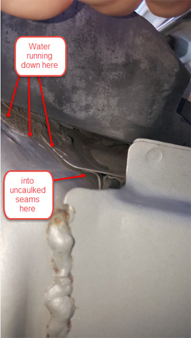
In regard to the top quarter of the seam, in my VX there was clear evidence of water running down the window pillar and under the rubber drip shield and from there it was easy for water to enter this uncaulked seam.
(photo 12)
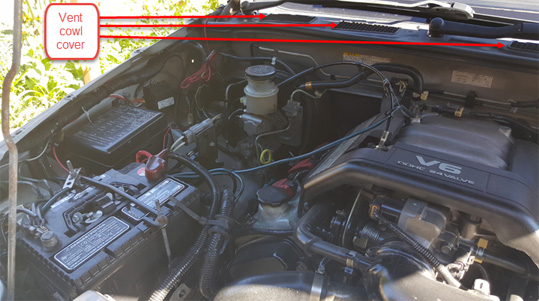
Along the bottom of the windshield is the black vent cowl cover
(photo 13)
beneath which the trough shaped cowl collects all water from the windshield and channels it to drain through a 2” hole at each side through the upper side cowl panels. (photos 14 & 15 viewed from the outside through the reinforced box section)
(Photo 14)
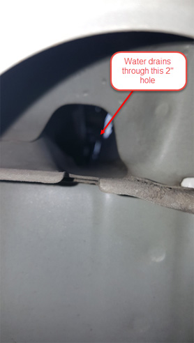
(Photo 15)
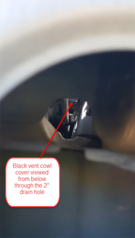
Depending on the camber of the road and whether the vehicle is pointing uphill or downhill, water does flow through the drain holes and down along this middle quarter section of the uncaulked seam.
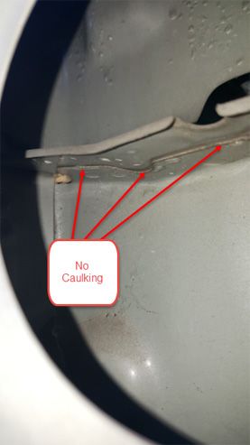
C. The horizontal spot welded seam between the top of the cowl side panel and the underside of the trough shaped cowl has no caulking either. (photos 16 & 17)
(Photo 16)
(Photo 17)
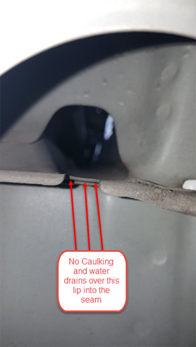
Normally this would not matter since the trough shaped cowl extends out to each side, over and beyond the top seam of the side cowl panel and curving down to form a drip edge. (photo 16 above) However, the drip edge has been interrupted by a 1” semicircular cut out directly in line with the 2” drain holes, allowing water to run back under the edge directly into the uncaulked seam. (photo 17 above) The alignment of the drain hole and the cut out would suggest that perhaps the designers intended for the fitment of a rubber drain hose to allow drainage directly to the wheel well.
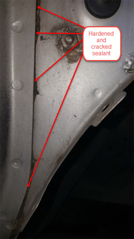
D. The fourth problem may be with the sealant material itself that was used between spot welded seams. Whether it is age or stress/flex, in this lower half of the seam, the material has hardened and shrunk, leaving what appear to be cracks (close-up photos 18 & 19)
(Photo 18)
(Photo 19)
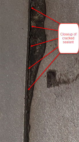
where water may be able to wick through to the interior. I did not go the extra mile to prove this out, preferring simply to go straight to the fix.
THE FIX !
After reading the lengthy problem details above, you will be happy to hear that the fix for Part I. is real easy, will only cost you about $6 and take up to 3 and ¾ hours of your time!
Tools you will need: Stubby and regular length Philips screwdrivers; flat head screwdriver; T30 Torx screwdriver (for 4 cladding screws); ¼” drive 10mm and 8mm sockets, ratchet wrench and 6” extension; a good dustpan brush and a couple of rags.
Supplies: one tube of good quality wicking silicone, the same that is used for sealing glass to rubber joints in windshields. This is liquid enough that it gets drawn into small cracks and seams and then sets.
You are going to be removing the front plastic cladding then the front fenders, both sides. Good news, you can remove the fenders without having to remove the cladding attached to them!
As mentioned above, because my VX is JDM (right hand drive), you may find it easier if you download all the photos first then flip them side to side so you can easily relate to the North American left hand drive.
Words of wisdom: (After the fact!)
Before you start, make sure you can open both doors wide to access some fasteners.
Even if you appear to only have a leak on one side, while you have the front cladding off, it is worth removing both fenders and treating both sides at the same time. Don’t make my mistake and fix one side only to find when you park on the other side of the road, the other carpet gets wet!
Keep the fasteners as close to the holes that they were removed from! There are some slight differences between them and this will make it much easier when you are putting everything back together.
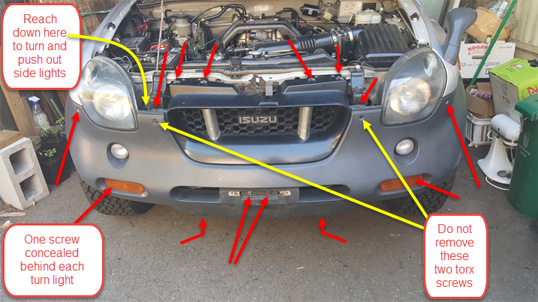
STEP 1 - Removal of front plastic cladding and grille in one piece. (15 minutes) There are a total of 18 fasteners holding the front cladding in place. (Arrowed in red - photos 20, 21 & 22)
(photo 20)
(photo 21)
(photo 22)
Do not attempt to remove the Torx screw between the grille and the headlight at each side (photo 21), these are dummy screws held to the cladding by a small rubber backing.
1) First remove and disconnect the parking lights. Turn anticlockwise to unlock and then pull forward. These can be tough suckers so you may need to reach down between the headlight and the radiator and behind the cladding to turn them and push them out. (Refer to photo 21)
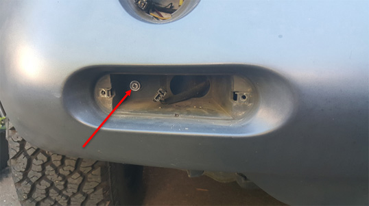
2) Next remove the turn signal lights and disconnect. Two Philips screws hold these in place.
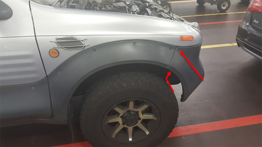
3) Behind each of these lights there is a single 10mm bolt securing the cladding to the metal bumper behind. Remove these bolts. You will need a socket extension to reach them. (photo 22)
4) Next, remove the two 10mm bolts behind the front license plate. (photo 21) If you have a front license plate or a cosmetic front skid plate, you will have to remove them first.
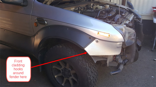
5) Now remove all remaining fasteners except the two bolts closest to the engine hood lock assembly that secure the grille. (photo 21) Move from one side to the other beginning with the 10mm self tapping bolt that secures the front cladding to the fender inside the wheel arch at the front. (photo 20)
6) The front cladding is now loosely hooked behind each fender at the wheel arch.
(photo 23)
Gently unhook one side, then supporting the weight of the cladding in the centre, remove the last two remaining bolts either side of the engine hood lock assembly. Hold the cladding either side of the grille (not the grille itself) (see photo 24)
(Photo 24)
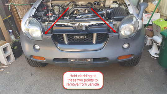
and lift forwards to remove it from the vehicle. The cladding can scratch easily so place on soft surface where you can’t trip over it!
STEP 2. Remove the plastic Inner Liners.
(photo 25)
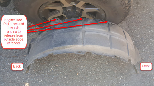
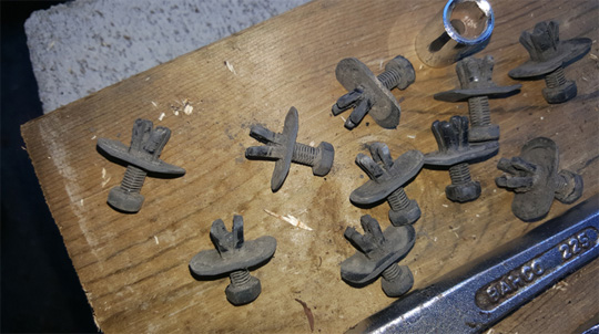
These are fixed inside of the wheel well above the tires with 10 plastic fasteners.
(photo 26)
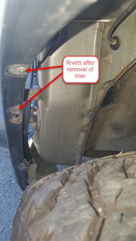
At first glance the liner looks as though it is riveted in place but this is not the case. (photo 27 of rivets after removal of inner liner)
(Photo 27)
The curb side edge of the liner is wedged between the cladding and the fender. The plastic fasteners push through a hole through all three layers and then expand on the other side of the hole when the centre plastic 8mm hex head screw/pin is screwed or pushed in. Use an 8mm socket to unscrew the centre pin while holding the body of the fastener until you can pull it free from the hole. Some of the centre pins may not unscrew at first, so you will need a knife or a flat head screwdriver to pry the pin out while you continue to unscrew it. Once you have removed all the fasteners, hold the engine side of the liner, (see photo 25 above) pull it down and towards the engine to release it from the curb side edge and remove from the wheel well. (This takes some effort! Fiddly to put it back too!)
End of SECTION 2. Continued in SECTION 3.

 Reply With Quote