Page 5 of 15 FirstFirst 1 2 3 4 5 6 7 8 9 ... LastLast
Results 61 to 75 of 216

Thread: Ascinder's 1-Ton VX... Cont'd

  1. #61
    Member Since
    Jan 2007
    Location
    VX Skeleton owner
    Posts
    1,190
    Thanked: 6
    I would absolutely love to do that, but I'm fresh out of room for a body and a frame in my meager garage. Justin and Bart will attest to this. My plan is to mock up the suspension under the VX using PVC pipes and the links so I can see how everything works and where it needs to bolt up, then when I get ready to weld I will drop the frame in place and support the body with the large yellow jacks. The trick is going to be making sure I have enough room for everything when it's all said and done.
    The reasonable man adapts himself to the world; the unreasonable man persists in trying to adapt the world to himself. Therefore all progress depends on me.

  2. #62
    Member Since
    Dec 2005
    Location
    Former Owner of 'ZEUS' aka 1031
    Posts
    3,185
    Thanked: 1
    Quote Originally Posted by Ascinder View Post
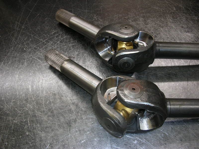
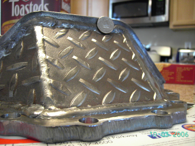
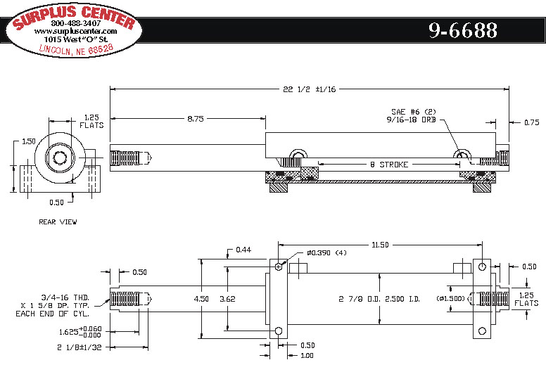
    No breakthroughs yet. I have been trying to pin down what I want to use for my Hydro steering and also been trying to find a good set of full hydraulic capable highsteer arms that have adjustable kingpin preload centercaps. What do you think about this idea? What I want to do is get the double ended arms like these:


    But instead of just getting one short and one double ended arm for crossover steering, I would get two double arms so that I could run the ram behind the differential, and a high mounted tierod across the front. The way I'm envisioning it is that the steering would be somewhat similar to a parallelogram, but one that would pivot off of the kingpin caps not the bases. Does that make sense? The only thing I'm running into is that I really don't like this picture:


    It looks like the hydro side of the parallelogram would not be a straight line and may cause things to act funny. I think it might just be in my head though. Common sense dictates that if I have two(four) points that are equidistant from their respective pivot points, that all the angles will stay the same-parallelogram style. In other words, as long as the distance(and angles) between the two forward steering arms stays the same, the rears have to match too, so even if the hydro steer diagrams look funky, they should still work right anyways with a tierod added across the backs. Maybe I'm overthinking/analyzing this stuff though.......
    I have thought about this after you brought up the potential issues and I think you are right to concern yourself. I'm not real sure of the severity though.

    The fault I see in the design is different than what you may have been concerned with though. I see the major issue as this... the linking rod that acts as a bridge between the two steering arms never adjusts in length while the rods at the ends of the plungers have to swivel to compensate for the throw of the steering arms. That swiveling motion would cause a subtle variation in length between the steering arms that would apply deflective pressure to the linking rod. I just created the basic concept with single lines in AutoCAD and in my sketch I noticed a difference of -5/16" in distance applied to the linking rod from the point of center (no steer) to 40 degrees of steer (using 10" arms from kingpin to arm end - so 20" total arm length).

    We could get much more accurate with what you are dealing with if you knew the length of the steering arms, the kingpin separation, the angle of max steering throw, the distance of separation between the ends of the plungers, and the location off axle center line to the center of the ram. I hope you know what I mean... The "more desirable" method in your illustration would lessen the degree of severity of the "most desirable" method because of the equal angle of the rods at the ends of the plungers during full lock and seemingly during the whole of the steering motion but there would most likely still be a variation in length.

    Remember when I asked you, "Why do we do this to ourselves?"? As always, I may or may not be correct!
    Last edited by ZEUS : 03/11/2010 at 01:13 PM
    Sent from my "two hands on a keyboard"

  3. #63
    Member Since
    Jan 2007
    Location
    VX Skeleton owner
    Posts
    1,190
    Thanked: 6
    I see what you are saying, but it just stands to reason that if the fronts of the arms must remain parallel so your tires are both steering the same axact angle, then the rears must too, does that make sense? That would mean that throughout the movement of the tie rods, as one increased it's arc, the other would simultaneously decrease it's arc at the same rate which I would think would balance out. The other issues I am having are that I was reading over at pirate that people have basically said this won't work in theory or on paper, but there are people running it problem free. It's very confusing trying to sort through all the contradictory information. I think I may make a model out of PVC and some plywood to real world test this. Also, I wanted to ask if you saw an incredibly big difference between the more desirable and most desirable mounting methods. They look about the same except the ram is deflected to the right in one and centered in the other. Another note is that most hydro steer arms I have heard of mount up on 8 or 9 inch centers. I dont know if that matters, but there you go, they did mention proper Ackerman angle as the reason for that though. Also the rams I have been looking at are typically 8" throws for ~40 degree steering and
    10" for 50 degree if you get the U joints machined. Here's also the prints for an example 8" ram(not the one I'm using, but close enough)


    The pivot centers of the kingpins are approximately 53.5" as I assume the forward tierod will be as well.. The tierods for the ram are obviously whatever lengths they need to be to set up properly. Hope this helps, I'm crossing my fingers.

  4. #64
    Member Since
    Mar 2008
    Location
    1999 (2001) Radiant Red 157/175 "lil pwny"
    Posts
    219
    Thanked: 0
    Just wondering mate when your done can you come over here and do mine

  5. #65
    Member Since
    Jun 2002
    Location
    1999, Ebony, VX, #1679
    Posts
    8,422
    Thanked: 3
    These would be sweet on that front 60...50 degrees of steering!

    Billy Oliver
    15xIronman
    My Sponsors:
    Accelerate3Coaching
    TriSports.com (PM me for 1 time use 20% off code)

  6. #66
    Member Since
    Jan 2007
    Location
    VX Skeleton owner
    Posts
    1,190
    Thanked: 6
    These would be sweet on that front 60...50 degrees of steering!
    I would have already bought those because they are priced around the same as upgrading to forged inner C's and knuckles, but the spidertrax setup requires two unit bearings at an additional cost of $740!!! Unit bearings are also not servicable, only replaceable, so if one goes out, so does your wallet I was thinking more along the lines of this for 50 degree steering:


    For $300 for the whole set, not too bad. I could also use the opportunity to upgrade to alloy alxles. This nice part is that they retain the maunfacturers warranty!!


    Just wondering mate when your done can you come over here and do mine
    Yeah, shoot me a plane ticket and put me up, and I'll do it.

  7. #67
    Member Since
    Dec 2005
    Location
    Former Owner of 'ZEUS' aka 1031
    Posts
    3,185
    Thanked: 1
    Well, Beau, I'm confusaled with ya! OK, the distance between the fronts of the arms related to the rears is always equidistant because of the design of the arms you are looking at eliminate the Ackerman principle... the "issue" that I bring up is that since 3 sides of the parallelogram are of static distance but one side is not, pressure is put on the tie rod - the weakest of the 4 sides. With what I just did in Cad, based off the dims you gave me, the deflection of the tie rod will be 7/32" or just over 3/16" with an 8" stroke. Because of this, I would say stay away from the long tie rod bridging the arms together. However, with those dims, you only get 31 degrees of steering if the ram was mounted 6" off axle center (which would be inline with the arm at 40 degree steer)! I just cannot see how they are getting 80 degrees of steer from lock to lock with an 8" stroke and an 8" straight arm! An 8" arm would need a 10" stroke to accomplish 40 degrees each way in this example because the Ackerman angle is nonexistent in the design of the arms. That is just what I have found - again, I could be wrong or missed something. PLEASE school me if you find out how they make it happen.

    Otherwise, in the case of the more desirable way and the most desirable way - I see little difference but it seems the more desirable way is simply the middle ground between the other two options. I'm going to go work on my Army truck now - it's far more simple!!!

    Do you have CAD? I can send to you what I have so you can see what I see happening... Happy researching!
    Quote Originally Posted by Ascinder View Post
    I see what you are saying, but it just stands to reason that if the fronts of the arms must remain parallel so your tires are both steering the same axact angle, then the rears must too, does that make sense? That would mean that throughout the movement of the tie rods, as one increased it's arc, the other would simultaneously decrease it's arc at the same rate which I would think would balance out. The other issues I am having are that I was reading over at pirate that people have basically said this won't work in theory or on paper, but there are people running it problem free. It's very confusing trying to sort through all the contradictory information. I think I may make a model out of PVC and some plywood to real world test this. Also, I wanted to ask if you saw an incredibly big difference between the more desirable and most desirable mounting methods. They look about the same except the ram is deflected to the right in one and centered in the other. Another note is that most hydro steer arms I have heard of mount up on 8 or 9 inch centers. I dont know if that matters, but there you go, they did mention proper Ackerman angle as the reason for that though. Also the rams I have been looking at are typically 8" throws for ~40 degree steering and
    10" for 50 degree if you get the U joints machined. Here's also the prints for an example 8" ram(not the one I'm using, but close enough)


    The pivot centers of the kingpins are approximately 53.5" as I assume the forward tierod will be as well.. The tierods for the ram are obviously whatever lengths they need to be to set up properly. Hope this helps, I'm crossing my fingers.

  8. #68
    Member Since
    Jan 2007
    Location
    VX Skeleton owner
    Posts
    1,190
    Thanked: 6
    Yeah I have cad, but the last time I turned it on was about a decade ago. I have Autocad 2004 and Solidworks 2003, but I haven't really messed with either. I'll try and take a look at it. People are accomplishing this somehow though, and have been for awhile now, so there must be something we are missing.

    Also, I think I found why this whole thing is confusing us: Ackerman steering

    I also read this guys thread and it looks like that if I run the behind the axle steering(the opposite of his) i would get better ackerman angles and therefore a better scrub radius!!! Also, I think I'm just going to get the 10" ram anyways since they can set the stops internally. I need to give this hydraulic steering guru over at pirate a call tomorrow. He has quite the reputation for squaring people away.
    Last edited by Ascinder : 03/11/2010 at 06:16 PM

  9. #69
    Member Since
    Jan 2007
    Location
    VX Skeleton owner
    Posts
    1,190
    Thanked: 6
    The mailman came today bearing gifts


    These things are ultra beef, and are literally bullet proof:

    http://www.jpmagazine.com/techarticl...est/index.html

    The covers are the last one in the shootout.

  10. #70
    Member Since
    Jan 2009
    Location
    97 Jap Import, Black BEAST
    Posts
    1,515
    Thanked: 0
    WOW!!!!!!

    Speed Thrills, Boredom Kills!!

  11. #71
    Member Since
    May 2006
    Location
    SOLD!
    Posts
    7,257
    Thanked: 2
    Yeah dude, you'll be making dust outta rocks with those! DAYUM.

    Bart

  12. #72
    Member Since
    Dec 2005
    Location
    Former Owner of 'ZEUS' aka 1031
    Posts
    3,185
    Thanked: 1
    Maybe this thread should be titled "Ascinder's 3 Ton VX"!

    At least it seems you'll have a low CG...

  13. #73
    Member Since
    Dec 2005
    Location
    Former Owner of 'ZEUS' aka 1031
    Posts
    3,185
    Thanked: 1
    Gotta any updates for us, Beau?

  14. #74
    Member Since
    May 2006
    Location
    SOLD!
    Posts
    7,257
    Thanked: 2
    Quote Originally Posted by ZEUS View Post
    Gotta any updates for us, Beau?
    I'm pretty sure he does...

    Bart

  15. #75
    Member Since
    Jan 2005
    Location
    2001, Ebony Black, 1153
    Posts
    2,264
    Thanked: 2

Similar Threads

  1. Ascinder breaks 30
    By Ldub in forum VX Talk...
    Replies: 6
    Last Post: 11/05/2012, 07:47 AM
  2. The return of Ascinder
    By Ascinder in forum VX Talk...
    Replies: 9
    Last Post: 01/27/2009, 11:51 AM

Posting Permissions

  • You may not post new threads
  • You may not post replies
  • You may not post attachments
  • You may not edit your posts
  •  
$lv_vb_eventforums_eventdetails