"I don't know why everyone is ignoring my 555 timer suggestion"
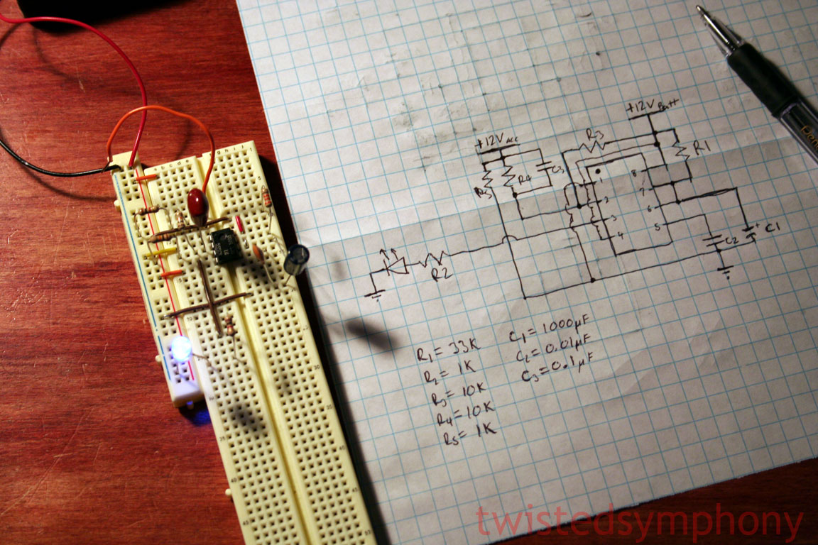
Right, the 555 is easy to use & is very versitile. I used one to build a sawtooth generator in college & used one once to build a pest repeller years ago. It's just a bit of overkill to use it for a timeout circuit (IMHO).
The real question is what to use to trigger the light to come on in the first place. I assume that you're not interested in a switch on the dash since they're hard to find in the dark. The most logical trigger in my mind would be the dome light. If the dome isn't triggered by turning off the ignition key (can't remember), it'll still come on as soon as he opens the driver door. You can still use the 555 astable multivibrator (that really is it's official name) to time it off at a different rate. It's also possible to use it for dimming an LED as well (PWM) but that would be more complex to design.


 Reply With Quote


")