Results 1 to 15 of 22

Thread: to the electrical guys..

Hybrid View

Previous Post Previous Post   Next Post Next Post
  1. #1
    Member Since
    May 2008
    Location
    1999 Astral Silver Metallic, 1802
    Posts
    219
    Thanked: 0
    Soldering some chips and other components to a small proto-board is actually EASIER than doing stuff like harness work. It look more difficult but really it's not.

    If you don't mind spending a little more you can buy whats called a "bread-board" which will let you build a prototype of your circuit by just plugging in the parts. NO SOLDERING REQUIRED


    it's as easy as building stuff with legos.

    Electronics are easy once you understand the basics. If you simply learn to read a circuit diagram you can build just about anything, you don't even need to understand the math behind it or why it works... All the diagram tells you is what parts are used and how they all connect together.

    a 555 timer circuit is quite simple and if you're even slightly interested in learning to build circuits or other little electronic projects then buying yourself a bread board a pack of resistor, a pac of capacitors, a pack of LEDs and a couple of 555 timers you'll have a lot of fun and realize just how easy this stuff is.

    I didn't even get into electronics until I was in college and I had a friend who was an EE, I had him explain what the different symbols were in circuit diagrams and it was a total eureka moment. spending $15 on a bread board and some pre-cut wire I stared building all kinds of stuff..


    That site I linked up top is awesome for beginners...
    check out this page for a quick list of basic components... http://www.kpsec.freeuk.com/symbol.htm

    you can also go here: http://www.kpsec.freeuk.com/compon.htm
    to see a comparison of what the symbols look like compared to the real life components (in most cases they're very similar)

    after looking at that, take a look at the diagram I posted again... it's really very simple.

    I'm happy to help answer questions on this stuff. Knowing how to read circuit diagrams will open up a world of possibilities for modifying your car.

  2. #2
    Member Since
    Jun 2004
    Location
    99 Astral Silver VX #1872 + 99 Ironman WIP
    Posts
    10,613
    Thanked: 1
    Quote Originally Posted by twistedsymphony View Post
    Soldering some chips and other components to a small proto-board is actually EASIER than doing stuff like harness work. It look more difficult but really it's not.

    If you don't mind spending a little more you can buy whats called a "bread-board" which will let you build a prototype of your circuit by just plugging in the parts. NO SOLDERING REQUIRED


    it's as easy as building stuff with legos.

    Electronics are easy once you understand the basics. If you simply learn to read a circuit diagram you can build just about anything, you don't even need to understand the math behind it or why it works... All the diagram tells you is what parts are used and how they all connect together.

    a 555 timer circuit is quite simple and if you're even slightly interested in learning to build circuits or other little electronic projects then buying yourself a bread board a pack of resistor, a pac of capacitors, a pack of LEDs and a couple of 555 timers you'll have a lot of fun and realize just how easy this stuff is.

    I didn't even get into electronics until I was in college and I had a friend who was an EE, I had him explain what the different symbols were in circuit diagrams and it was a total eureka moment. spending $15 on a bread board and some pre-cut wire I stared building all kinds of stuff..


    That site I linked up top is awesome for beginners...
    check out this page for a quick list of basic components... http://www.kpsec.freeuk.com/symbol.htm

    you can also go here: http://www.kpsec.freeuk.com/compon.htm
    to see a comparison of what the symbols look like compared to the real life components (in most cases they're very similar)

    after looking at that, take a look at the diagram I posted again... it's really very simple.

    I'm happy to help answer questions on this stuff. Knowing how to read circuit diagrams will open up a world of possibilities for modifying your car.
    COOL !...Thanks, I'll look into that later, gotta go work now.

  3. #3
    Member Since
    May 2008
    Location
    1999 Astral Silver Metallic, 1802
    Posts
    219
    Thanked: 0
    If you're interested in picking this stuff up here's what you can get from RadioShack to get you Started.

    looking at radioshack's website you can pickup a bread board for about $8
    http://www.radioshack.com/product/in...entPage=search

    you'll also want to buy a set of pre-cut wires for the board another $7
    http://www.radioshack.com/product/in...entPage=search

    this will give you oodles of wires pre-cut and stripped for easy use on a bread-board, trust me, it's worth it.

    Then pickup a battery holder of some sort (need to power your circuit), I recommend one that holds 4 AA batteries since that will give you roughly 5V of power which is perfect for most projects. http://www.radioshack.com/product/in...entPage=search

    If you're building car circuits you'll also want to pick up a "7805" power regulator. Which will take the 12V from the car as an input and output 5V for your circuit. http://www.radioshack.com/search/ind...regulator&sr=1

    you'll only need to use this part when hooking it up to your car, this component is very popular more info here: http://www.kpsec.freeuk.com/powersup.htm#regulator One thing to be weary of is this part can get hot since it burns off the extra energy as heat. The 555 circuit probably wont draw much though so it might not even be a concern for this project.

    Then just pickup whatever other parts you need for your particular project and go to town plugging stuff in and experimenting.

    if you really want you could just leave the bread board right in your car, lots of people leave their projects like that and most bread boards have double sided sticky tape on the bottom for just such an occasion. I would recommend transferring your circuit to a regard proto-board and soldering it in place once you're happy with it though, since it's a lot more permanent and you don't have to worry about things falling out, then you can re-use your bread board for your next project.

  4. #4
    Member Since
    Feb 2007
    Location
    2000 Proton VX - 0776
    Posts
    9,258
    Thanked: 0
    "I don't know why everyone is ignoring my 555 timer suggestion"

    Right, the 555 is easy to use & is very versitile. I used one to build a sawtooth generator in college & used one once to build a pest repeller years ago. It's just a bit of overkill to use it for a timeout circuit (IMHO).

    The real question is what to use to trigger the light to come on in the first place. I assume that you're not interested in a switch on the dash since they're hard to find in the dark. The most logical trigger in my mind would be the dome light. If the dome isn't triggered by turning off the ignition key (can't remember), it'll still come on as soon as he opens the driver door. You can still use the 555 astable multivibrator (that really is it's official name) to time it off at a different rate. It's also possible to use it for dimming an LED as well (PWM) but that would be more complex to design.
    [SIGPIC][/SIGPIC]

    Put a smiley after you say that Bub.

  5. #5
    Member Since
    May 2008
    Location
    1999 Astral Silver Metallic, 1802
    Posts
    219
    Thanked: 0
    Quote Originally Posted by tom4bren View Post
    "I don't know why everyone is ignoring my 555 timer suggestion"

    Right, the 555 is easy to use & is very versitile. I used one to build a sawtooth generator in college & used one once to build a pest repeller years ago. It's just a bit of overkill to use it for a timeout circuit (IMHO).

    The real question is what to use to trigger the light to come on in the first place. I assume that you're not interested in a switch on the dash since they're hard to find in the dark. The most logical trigger in my mind would be the dome light. If the dome isn't triggered by turning off the ignition key (can't remember), it'll still come on as soon as he opens the driver door. You can still use the 555 astable multivibrator (that really is it's official name) to time it off at a different rate. It's also possible to use it for dimming an LED as well (PWM) but that would be more complex to design.
    whoa whoa whoa...

    I think you're missing HOW I was suggesting to use the 555 timer...

    "Monostable mode" does EXACTLY what we're looking for here..

    it gets a trigger, then it outputs a solid on signal for X amount of time.. then it turns off the output and waits for a trigger again.

    this is exactly what we're looking for. the signal is when the ignition turns off. when that happens the LED comes on for X amount of time... then the LED turns off and waits for an signal again.

    If you attach it to the dome light for a signal then the design has already failed because the intent is to help the passenger find the interior door handle BEFORE the door is opened... the dome light comes on AFTER the door is opened... at which point you don't need to find it anymore

    As for the trigger...
    the 555 timer has a trigger input... the cool thing about how it works really nicely with this setup.. is that the 555 is activated on the "trailing end" of the trigger pulse. what does this mean?

    I means when the car is off the Ignition/ACC signal is at 0V... then when you start the car it goes up to 12V, This is the LEADING edge of the "trigger pulse" (it just happens that this single "pulse" lasts the duration of the car ride). When you turn the car off the Ignition/ACC signal drops back down to to 0V, this is the TRAILING edge of the "trigger pulse". Since the 555 does it's thing on the trailing edge of the trigger pulse it turns on the LED the instant the Ignition/ACC signal drops down to 0V. PERFECT

    A 555 timer triggered from the ACC line in the VX and wired in monostable mode with an output to an LED would work like this:

    -The VX is off and so is the LED
    -you start the car and go for a drive... the LED is still off
    -you park it and leave it running... the LED is still off
    -You turn the key off ... the LED comes on and stays on
    -the LED turns off after a set amount of time.
    -repeat

    I don't know but IMO that seems to be EXACTLY what we're looking for an EXACTLY the kind of application the 555 was built to be used for.


    If you want to add a fade effect to that where the LED comes on instantly stays on for a few seconds, and then fades out, you'll just need to add a transistor and capacitor between the output of the 555 and the LED.
    Last edited by twistedsymphony : 09/24/2008 at 10:58 AM

  6. #6
    Member Since
    Feb 2007
    Location
    2000 Proton VX - 0776
    Posts
    9,258
    Thanked: 0
    OK - in my head I was just making it more complicated than it was.

    Dome light is still OK since he said it was the passenger & not him that couldn't find the handle.

    Your application might be better for the blind date scenario since he wouldn't be getting out to open her door. But on the other hand, he prolly wouldn't be shutting off the engine either.

    Actually, I've met Eric's GF & she's a keeper so he knows I'm just kidding.

    I guess he could trigger the 555 from pwr ant lead from his head unit & get the same effect.

  7. #7
    Member Since
    May 2008
    Location
    1999 Astral Silver Metallic, 1802
    Posts
    219
    Thanked: 0
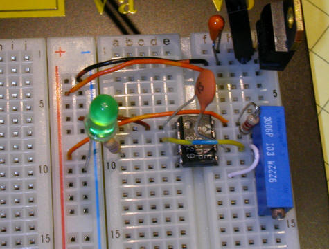
    if I have time I'll whip up the circuit and take some pics, I've got a whole freekin handful of 555 timers in my parts bin

Similar Threads

  1. Zero electrical power?
    By blacksambo in forum VX Troubleshooting...
    Replies: 10
    Last Post: 04/22/2014, 01:14 PM
  2. Electrical Problems
    By dmanske@cavtel.net in forum VX Talk...
    Replies: 7
    Last Post: 01/04/2012, 07:02 AM
  3. So what it be guys? lomg time sence i've talked to u guys...
    By CoastieCosta567 in forum Chit-Chat ...
    Replies: 7
    Last Post: 02/20/2010, 12:23 AM
  4. Dead VX, Seems Electrical
    By jbregar in forum VX Troubleshooting...
    Replies: 9
    Last Post: 09/20/2004, 10:04 AM
  5. Electrical Problems...
    By Jolly Roger VX'er in forum VX Talk...
    Replies: 7
    Last Post: 08/18/2003, 01:32 PM

Posting Permissions

  • You may not post new threads
  • You may not post replies
  • You may not post attachments
  • You may not edit your posts
  •  
$lv_vb_eventforums_eventdetails