Results 1 to 15 of 22

Thread: to the electrical guys..

Hybrid View

Previous Post Previous Post   Next Post Next Post
  1. #1
    Member Since
    Feb 2006
    Location
    2001,Kaiser Silver, VX, 0563
    Posts
    4,767
    Thanked: 0
    phew! i stepped away for a couple days and yall are arguing at my expense

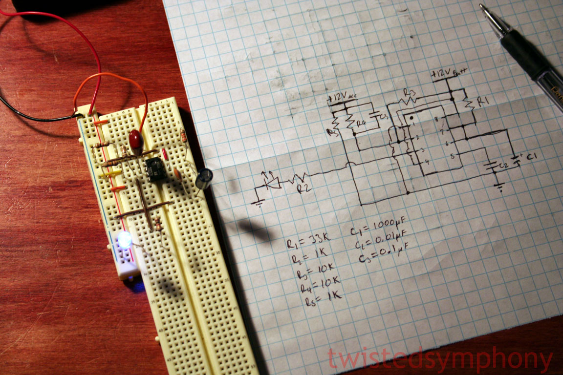
    the 555 timer is sounding better and better... i would love a quick circuit diagram if you could whip one up for me.. i already have most of the components i need.. a few of my classes required me to learn that kind of stuff.. ive built wii remotes using accelerometers.. speedometers using solonoid pulses... scales using whetstone bridges blablabla

    tom, i thought about using the dome light.. but what i had planned to do was to find a circuit that would not draw power.. and use a relay that outputs to 87a when there it is not activated.. and outputs to 87 when it is activated.. that way i will just have an ignition wire activate it so that when the car is on.. there is no power to the 87a terminal (which would control the lights) then as soon as i turn the car off, the 87a terminal would be live... problem with that would have been it would be constant draw on the system unless i figured out a way to cut it off after so long... (btw.. the girlfriend you met.. wasnt as much of a keeper as we thought... long story.. but theres recently a new girl in town.. ill bring her by next time!)

  2. #2
    Member Since
    May 2008
    Location
    1999 Astral Silver Metallic, 1802
    Posts
    219
    Thanked: 0
    I drew up a quick diagram of the 555 circuit that will run the LEDs for 30 seconds and then fade out when you turn the car off..

    I'll have to wait until I get home before I can scan it in to share with everyone.... if I have time tonight I'll wire it up and make sure it works

  3. #3
    Member Since
    May 2008
    Location
    1999 Astral Silver Metallic, 1802
    Posts
    219
    Thanked: 0
    As promised...


    I ran into a little snafu initially, I didn't realize that the 555 required a "pulse" for the trigger meaning that if the power went from high to low and didn't go back high it would "continue to trigger" meaning the LED would stay on...

    I got around that by adding a simple "RC" circuit to the trigger... now it works as designed.

    There are essentially 4 wires that connect to this circuit
    -12v constant (from the batter)
    -ground
    -12V switched (the accessory wire) and
    -the LED output signal

    if you look at the picture you can see the red and black wires up top... power and ground. the big loose orange wire is the "accessory" which I would switch by simply touching it to power and the unplugging it to simulate the car turning off. and the LED I attempted to visually separate from the rest of the circuit a bit.

    you can mount this somewhere in the dash and run two wires from the output, one to each door to act as the power signal for the LED... the ground for the LED can just be grounded to anything metal in the door.

    If I still had a working video camera I'd make a short video showing it in action.

Similar Threads

  1. Zero electrical power?
    By blacksambo in forum VX Troubleshooting...
    Replies: 10
    Last Post: 04/22/2014, 02:14 PM
  2. Electrical Problems
    By dmanske@cavtel.net in forum VX Talk...
    Replies: 7
    Last Post: 01/04/2012, 08:02 AM
  3. So what it be guys? lomg time sence i've talked to u guys...
    By CoastieCosta567 in forum Chit-Chat ...
    Replies: 7
    Last Post: 02/20/2010, 01:23 AM
  4. Dead VX, Seems Electrical
    By jbregar in forum VX Troubleshooting...
    Replies: 9
    Last Post: 09/20/2004, 11:04 AM
  5. Electrical Problems...
    By Jolly Roger VX'er in forum VX Talk...
    Replies: 7
    Last Post: 08/18/2003, 02:32 PM

Posting Permissions

  • You may not post new threads
  • You may not post replies
  • You may not post attachments
  • You may not edit your posts
  •  
$lv_vb_eventforums_eventdetails