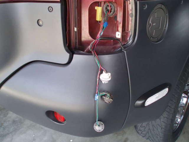
L.E.D. Flashers Woes; Mystery disconnect harness
Hi, folks,
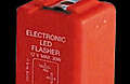
I got my electronic L.E.D. flasher today from superbrightleds.com in hopes of eliminating the “hyper flash” without having to run in-line resistors.
http://www.superbrightleds.com/tail-brake-turn.html (down on the page)
After contorting myself and wrestling the huge wire harness trunk that prevented removal of the stock flasher, I installed the L.E.D. flasher only to have my 15amp turn-signal fuse blow when I turned the ignition key to the “on” position. I replaced the fuse and reinserted the stock flasher to make sure all was fine. Then I tried again with the L.E.D. flasher in, blow a 20amp fuse.
Anyway, does anyone have a proven L.E.D. flasher and source that does work. Odds are that it is not just a bad unit, but improper for the job. The flasher specs on the side seems to be within limits, but blows the fuse. John (rowhard), I believe, is running this flasher just fine, but I’m willing to try an alternative if anyone has the information.
The superbright.com flasher:
The stock flasher:

As a bonus question, can anyone identify this harness that I found tucked up in the left side kick panel? I assume it is for the front round driving lights, which I have never seen on, on my VX. It has a 5amp in-line fuse and 3 wires running to the 5-pronged plug: red, yellow and black. Where does this plug in? It’s long and looks like it could reach somewhere in the left-foot floor kick panel cover area. I wasn’t able to get the left kick panel cover off without plastic damage, as my metal, gold-colored, retaining clips had sprung wide open beneath. It’ll take more surgery to safely remove the cover. 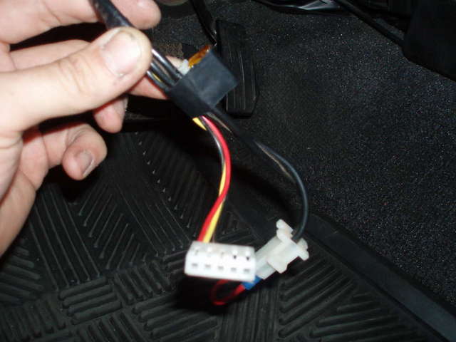
Bren Workman
Gretna, NE
(C) 402-312-1992
[SIGPIC][/SIGPIC]


 Reply With Quote